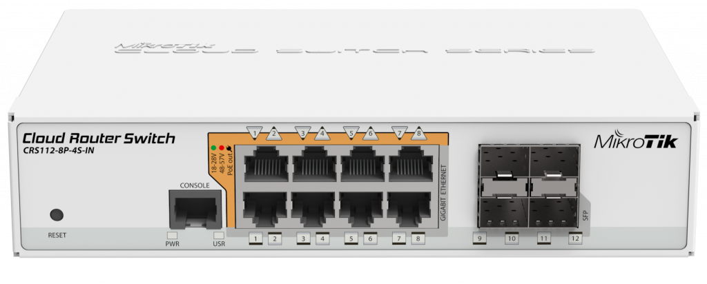
Lets look at configuring a CRS1XX or 2XX series Cloud Router Switch and how to configure trunking.
First we need to look at the basics setting up a bridge but this is purely to pass all over to the internal switching to off load vlan support you find this is the same or similar to the fallowing chipsets: QCA8337, Atheros8327, Atheros8316, Atheros8227 and Atheros7240.
This table below breaks down what each switch chip is capable of and there limitations.
| Feature | QCA8337 | Atheros8327 | Atheros8316 | Atheros8227 | Atheros7240 |
|---|---|---|---|---|---|
| Port Switching | yes | yes | yes | yes | yes |
| Port Mirroring | yes | yes | yes | yes | yes |
| TX limit | yes | yes | yes | yes | yes |
| RX limit | yes | yes | no | no | no |
| Host table | 2048 entries | 2048 entries | 2048 entries | 1024 entries | 2048 entries |
| Vlan table | 4096 entries | 4096 entries | 4096 entries | 4096 entries | 16 entries |
| Rule table | 92 rules | 92 rules | 32 rules | no | no |
Well that’s a little bit on the background (if any) and we really should get down the configuration. lets say you are fairly used to using SSH or the Telnet as a standard. Personally you learn more by typing out each command (but copy and pasting is a time saver..)
First we need to create a bridge with no spanning Tree protocol enabled, usually you have the options for STP, RSTP and MSTP for more information on spanning tree and its uses click here
First Create a Bridge:
/interface bridge add name=bridge protocol-mode=none
Next we need to add ports to bridge with hardware offloading enabled this is to pass the workload directly to the switch chip instead of the processor.
/interface bridge port add bridge=bridge interface=ether1 hw=yes add bridge=bridge interface=ether2 hw=yes add bridge=bridge interface=ether3 hw=yes add bridge=bridge interface=ether4 hw=yes add bridge=bridge interface=ether5 hw=yes add bridge=bridge interface=ether6 hw=yes add bridge=bridge interface=ether7 hw=yes add bridge=bridge interface=ether8 hw=yes add bridge=bridge interface=sfp9 hw=yesadd bridge=bridge interface=sfp10 hw=yesadd bridge=bridge interface=sfp11 hw=yesadd bridge=bridge interface=sfp12 hw=yes
Now after adding the ports to the bridge you need to look at the trunk ports
Little bit of information about trunk ports, it’s important to understand when and where to use them for example; If you have a large amount of data passing across multiple ports And you need to back haul it to a centralised location then it’s worth using trunk ports. This is where you take more than one port and group them together to act as if they are one large port. This is where trunking becomes quite an advantage.
Do not get me wrong, trunking can have some limitations but the limitations certainly outweigh the advantages.
This is something that is always worth taking into consideration when your designing a network knowing what the potential future may hold in a lot of cases. If you have a switch that has multiple ports for trunking it’s worth just trunking them in the first place. To save your time later again it’s something we will talk in more detail later on.
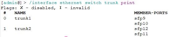
Lets get on with the next stage creating a trunk let’s say we want to trunk ports sfp9 and sfp10 together to make one trunk? First we will need to access the switch and simply add ports to a trunk with a name in this case I’m using the name of trunk1.
/interface ethernet switch trunk
add member-ports=sfp9,sfp10 name=trunk1
Some people like to list the ports within the name (trunk1-sfp9-sfp10) to make it easier at a glance but it’s quite easy to view what ports which are attached. Plus if someone has been messing with or has got the port names wrong your best bet is to just print out the setup trunks.
What we have done here is create a trunk with the name of trunk1 by adding sfp9 and sfp10 to quite literally bond them together to create 1 port. you can add more and depending on the limit available you can add more to the group. in the case of the CRS112 you can add all 4 sfp ports and aggregate them all into one trunk which can be a handy feature for a rugged switch like this CRS112 for high quality CCTV or high traffic radio throughput or some switch aggregation point I don’t know but it could work.
At that’s that there is not much else to say it’s quite simple to setup a trunk on the CRS1XX and CRS2XX series switches but be mindful on the configuration require on the other side for the aggregation to work on a Mikrotik Router that supports port bonding.
/interface bonding
add mode=balance-xor name=bond1 slaves=ether1,ether2\
transmit-hash-policy=layer-2-and-3
the default setup would look something like this
/interface bonding name="bonding1" mtu=1500 mac-address=00:00:00:00:00:00 arp=enabled arp-timeout=auto
slaves=combo1,sfp-sfpplus1 mode=balance-xor primary=none link-monitoring=mii arp-interval=100ms
arp-ip-targets="" mii-interval=100ms down-delay=0ms up-delay=0ms lacp-rate=30secs
transmit-hash-policy=layer-2-and-3 min-links=0
Little bit of a background on the above configuration, combo1,sfp-sfpplus1 are both sfp ports stands for Small form-factor pluggable, or SFP for short, devices are hot-swappable interfaces used primarily in networking to connect devices between varying distances.
A combo port which I have only really come across with Mikrotik routers are either ethernet or sfp ports. In the case above there is also a sfp plus (sfp+) port which offers speeds up to 10Gbits capable link upto 300m on Multimode and 40 kilometers on single-mode but this can vary widely depending on the cable classification.